 Bharat Jayaraman
580 California St., Suite 400
San Francisco, CA, 94104
1996, Proceedings 1996 IEEE Symposium on Visual Languages
https://doi.org/10.1109/VL.1996.545264…
8 pages
The motivation for this work stems from the lack of good visual tools for describing the execution of procedure-level constructs such as procedures, functions, coroutines, iterators, methods, and processes. Our proposed solution to this problem is an extension of an old technique called the contour diagram, which was originally used to give semantics for Algol-like languages. Our extensions allow the contour diagram to be used for more modern languages, such as object-oriented languages, logic languages, etc. In this paper, we explain this extended notation, and its use in visualizing the execution of procedural, object-oriented and logic programs. The significance of this extension is that it can serve as a basis for program visualization tools.
AI


Hristov, H., „Review and outlooks of the means for visualization of syntax semantics and source code. Procedural and object oriented paradigm – differences”, Anniversary International Conference REMIA 2010, Plovdiv, 2010, pp. 443-450, ISBN 978-954-423-648-9, 2010
In the article, we have reviewed the means for visualization of syntax, semantics and source code for programming languages which support procedural and/or object-oriented paradigm. It is examined how the structure of the source code of the structural and object-oriented programming styles has influenced different approaches for their teaching. We maintain a thesis valid for the object-oriented programming paradigm, which claims that the activities for design and programming of classes are done by the same specialist, and the training of this specialist should include design as well as programming skills and knowledge for modeling of abstract data structures. We put the question how a high level of abstraction in the object-oriented paradigm should be presented in simple model in the design stage, so the complexity in the programming stage stay low and be easily learnable. We give answer to this question, by building models using the UML notation, as we take a concrete example from the teaching practice including programming techniques for inheritance and polymorphism.
A classic notion in logic programming is the separation of logic and control. Logic is for problem solving; control is for directing inference. However, practical experience in the classroom suggests that problem-solving students nonetheless devote much effort to understanding control issues such as eliminating looping behaviours and improving program efficiency. In the case of Prolog, this requires a clear understanding of the operation of both unification and backtracking. Students often try to get this understand by tracing executions, but the common fourport debugger used in Prolog is not as helpful as it could be. In particular, it provides information in low bandwidth textual form. This paper describes a new visualization system for logic programming that uses colour tagging to trace unification through the Prolog proof tree. A user can dynamically "tag" a term or subterm with a colour that is immediately propagrated through the displayed tree. The colour is also pro...
1999
Representing abstract data structures in a real programming language is a key step of algorithm implementation and often requires programmers to introduce language-dependent details irrelevant for both a high-level analysis of the code and algorithm comprehension.
Proceedings of the 36th annual Southeast regional conference on - ACM-SE 36, 1998
For years researchers have sought to find a way to make programs easier to understand. They have developed flowcharting techniques and even movies to show the flow of a program. It is a generally accepted notion that these tools make programs easier to understand. Current research in software visualization has resulted in the development of algorithm animation systems. These systems allow students to see the execution of a program. Several studies have been performed with mixed results. In this study, the author seeks to find if use of one of two particular animation systems effects understanding of an algorithm. This study also seeks to determine if students have a preference for one of the two tools. The results show that there is no significant difference between the two tools on understanding and application of an algorithm. There is however a preference for DynaLab over the GAIGS as an algorithm animation system for understanding of list concepts and for general use. There is no preference between the tools for use with recursive algorithms.
2009
The aim of this paper is to show the approaches involved in the implementation of two tools of PCVIA project that can be used for Program Comprehension. Both tools use known compiler techniques to inspect code in order to visualize and understand programs' execution but one of them modifies the source code and the other not. In the non-invasive approach, we convert the source program into an internal decorated (or attributed) abstract syntax tree and then we visualize the structure traversing it, and applying visualization rules at each node according to a pre-defined rule-base. No changes are made in the source code, and the execution is simulated. In the invasive approach, we traverse the source program and instrument it with inspection functions. Those functions, also known as inspectors, provide information about the function-call flow and data usage at runtime (during the actual program execution). This information is collected and gathered in an information repository that is then displayed in a suitable form for navigation. These two different approaches are used respectively by Alma (generic program animation system) and CEAR (C Rooting Algorithm Visualization tool). For each tool several examples of visualization are shown in order to discuss the information that is included in the visualizations, visualization types and the use of Program Animation for Program Comprehension.
In Proc. 1-st Workshop on …, 1997
In this paper we present a new software visualization tool, called LEONARDO, which allows to visualize algorithms on graphs (but is easily extendable to other kinds of data structures). LEONARDO's main peculiarities are a complete use of the undo/redo mode, bounded only by the potentiality of the working machine, and a mapping between concrete and abstract data structures allowed by a new logic visualization language.
1989
The structure of a parallel program is considerably more difficult to visualize and understand than that of a sequential one. Pictorial methods can help make the structure more visible. In this paper I describe a pictorial representation of occam programs. This representation has been developed as part of the Alvey ParSiFal project, for use by one of its tools, GRAIL.
International Joint Conference on Artificial Intelligence, 1991
This paper describes the development of an architecture and implementation of a graphical tracing system for the parallel logic programming language PARLOG. Novel features of the architecture include a graphical execution model of PARLOG; a range of representational techniques that allow the user a choice of perspective and granularity of analysis; and ongoing work on graphical tools that provide user-defined visualisations of their programs, either before the program is run, or afterwards by demonstration from a textual trace. The aims of the architecture are threefold: (1) to aid program construction and debugging by providing an informative graphical trace of the program's execution; (2) to provide the user with a choice of representational techniques, at a preferred level of granularity; and (3) to allow users to define their own visualisations, that more truly map onto their conception of the problem, and which support the way they wish to view the execution information.
2008
One of the definitions for visualization is to give a visible appearance to something, making
AI
The paper demonstrates that contour models clarify object environments by visually representing variable scoping, making it easier to trace method calls and inheritance interactions. This visual structure is particularly beneficial for managing dynamic memory allocation in object-oriented languages.
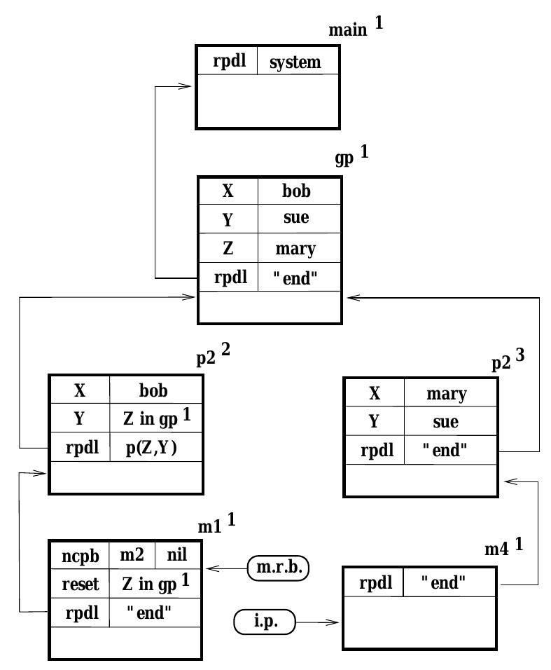
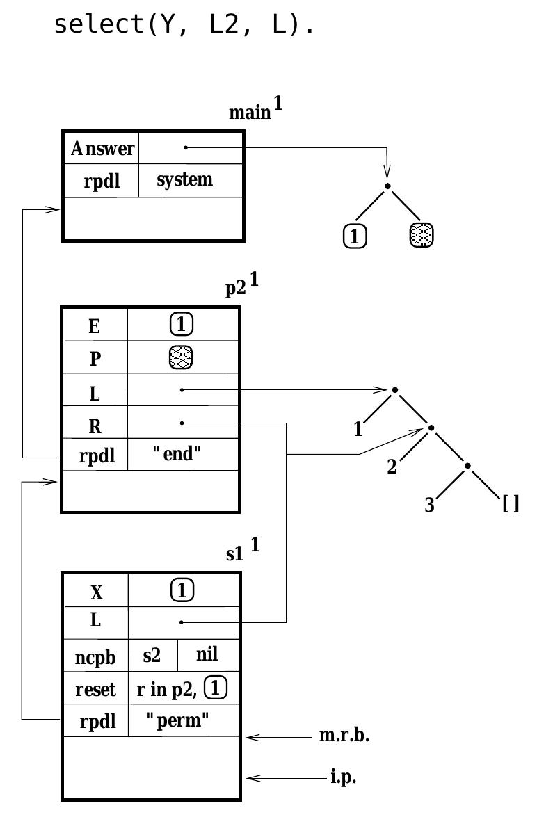
Contour diagrams for logic programs introduce fields to track backtracking and unification, easily visualizing the proof tree structure. This allows for a clearer understanding of alternative resolutions and dynamic variable bindings during execution.
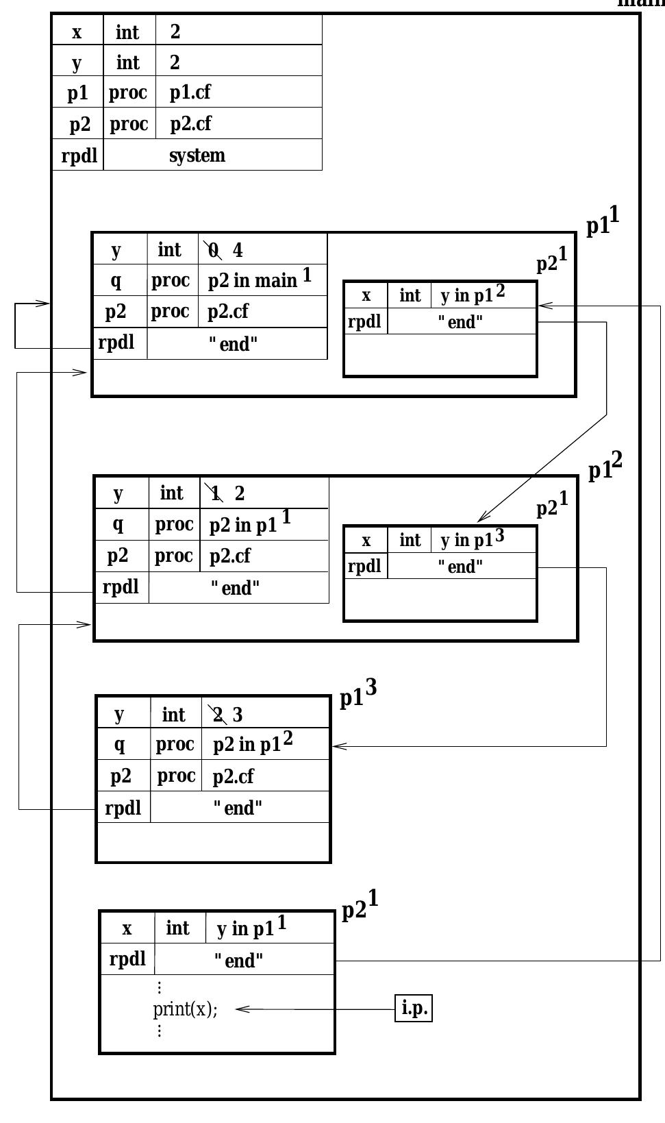
The contour model provides a pictorial representation of program execution, enhancing clarity over traditional textual operational semantics, which can obscure scoping and execution flow. This method emphasizes understanding procedure calls and variable bindings, contrasting sharply with lower-level stack-based representations.
Recursion in statically-scoped languages is depicted through nested contours, where identifiers maintain visibility across multiple invocations, fostering clarity in scope management. Each procedure call generates a new contour to track unique execution contexts without losing association with declared identifiers.
Contour models have been successfully adapted for object-oriented and logic programming languages, enhancing visualization tools for concurrent programming and complex parameter interactions within modern software structures. The adaptability of the contour model supports advanced features like dynamic data object tracking and inheritance.
Software Visualisation, 1996
Program visualisation focuses on the graphical representation of an executing program and its data. The information is presented in a form designed to enhance both the understanding and productivity of the programmer through the e cient use of the human visual system. The programmer is able to observe patterns of behaviour within the executing code and rapidly detect a departure from the expected behaviour pattern. However, depending on the programming paradigms and architectural platforms utilized, the variety and manner in which information is best presented varies. This chapter attempts to discuss the general aspects of program visualisation, including the variety of purposes, the general steps needed to provide such visualisation, and the ideals that a program visualisation tool can achieve. The requirements for visualization systems also vary across architectural platforms, and software systems, which include programming paradigms and the system environment. Some representative visualisation systems are also presented and examined, providing an overall view of the practice and the achievements made to date in program visualisation.
Proceedings of TENCON '93. IEEE Region 10 International Conference on Computers, Communications and Automation, 1993
This paper illustrates the variety of visualization techniques that are employed for various programming paradigms, examining the type of information required and the advantages that the information provides the programmer. We examine the specific visualization requirements for each paradigm and the general requirements of visualization systems which depict the flow of control for both sequential and parallel program execution. We find that many of the visualization systems currently available tend to focus on only one aspect of the visualization requirements rather than the broad base of needs of the programmer. The need to integrate these visualization systems in the future is highlighted.
2008
The aim of this paper is to show the strategies involved in the implementation of two tools of PCVIA project that can be used for Program Comprehension. Both tools use known compiler techniques to inspect code in order to visualize and understand programs' execution. On one hand we convert the source program into an internal decorated (or attributed) abstract syntax tree and then we visualize the structure traversing it, and applying visualization rules at each node according to a pre-defined rule-base. No changes are made in the source code, and the execution is simulated. On the other hand, we traverse the source program and instrument it with inspection functions. Those inspectors provide information about the function-call flow and data usage at runtime (during the actual program execution). This information is collected and gathered in an information repository that is then displayed in a suitable form for navigation. These two different approaches are used respectively by Alma (generic program animation system) and Cear (C Rooting Algorithm Visualization tool). For each tool several examples of visualization are shown in order to discuss the information that is included in the visualizations, visualization types and the use of Program Animation for Program Comprehension.
ACM SIGCSE Bulletin
2007
The aim of this paper is to discuss how our pattern-based strategy for the visualization of data and control flow can effectively be used to animate the program and exhibit its behavior. That result allows us to propose its use for Program Comprehension. The animator uses well known compiler techniques to inspect the source code in order to extract the necessary information to visualize it and understand program execution. We convert the source program into an internal decorated (or attributed) abstract syntax tree and then we visualize the structure by traversing it, and applying visualization rules at each node according to a pre-defined rule-base. No changes are made in the source code, and the execution is simulated. Several examples of visualization are shown to illustrate the approach and support our idea of applying it in the context of a Program Comprehension environment.
2000
Code development for projects that are not trivial is time consuming and difficult. A well structured approach is essential to produce satisfactory results. One major problem facing the programmer is the need to conceptualize the structure of the program that is being written or maintained in order to completely understand the program while browsing it's source listing. This problem may be overcome by providing a tool that allows code to be browsed within the confines of a visual representation of the program's structure. This paper reviews the requirements for a tool to provide such a mechanism and describes the design of DUCAT (Deakin University C Analysis Tool) which addresses these requirements. DUCAT provides a call graph of a program and allows the user to browse functions individually by interacting with the call graph.
Software engineering education and training has obstacles caused by a lack of basic knowledge about a process of program execution. The article is devoted to the development of special tools that help to visualize the process. We analyze existing tools and propose a new approach to stack and heap visualization. The solution is able to overcome major drawbacks of existing tools and suites well for analysis of programs written in Java and C/C++.
In this paper we present an algorithm for drawing execution graphs. Such graphs represent the control flow in a program. The fact that a program is constructed according to a grammar is reflected in the corresponding execution graph. Therefore, we introduce graph production rules that are based on generally used programming language constructs. Each rule is applied to a certain class of topologies of the graph. By parsing an execution graph according to these rules a visually appealing layout of the graph can be generated. We take into account that the nodes in a graph can have variable sizes. Fonnalizing Process Algebraic Verifications in the Calculus of Constructions. p. 49. Concrete process algebra. p. 134.
Proceedings IEEE Symposia on Human-Centric Computing Languages and Environments (Cat. No.01TH8587)
In the context of Alma (a system for program visualization and algorithm animation), we use an internal representation-based on the concept of an attributed abstract syntax tree decorated with attribute values, a DAST -to associate (static) figures to grammar rules (productions) and to step over program dynamics executing state changes in order to perform its animation. We do not rely upon any source program annotations (visual/animation statements, or parameters), neither on any special visual data types. On account of such principle, the approach becomes source language independent. It means that we can apply the same visualizer and animator, that is the Alma 's back-end, to different programming languages; all that we need is different front-ends to parse each program into the OAST we use. In this paper we discuss Alma design goal.s and architecture, and we present the two mappings that associate to productions figures and rewriting rules to systematically draw a visual representation (exhibiting data and control flow) of a given source program and to animate its execution.
1988
Logic programs have traditionally been described by means of 'AND/OR' trees. The AORTA diagram is an And/OR Tree, Augmented to include invocation history 'status boxes' at each node. This augmentation makes it possible to present a graphical view of Prolog execution which is very compact, yet which contains complete details of unification and control history, including multiple (backtracking) invocations and extra-logical features such as the cut. The notation described herein serves as the uniform basis for textbook diagrams, video-based animations, and an advanced tracing and debugging facility running on modern graphics workstations.